Juice4halt
the batteryless Micro-UPS for Raspberry Pi
and other 5V Single Board Computers
Features
no batteries - the Juice4halt modules use supercapacitors instead of batteries
- no maintenance - no batteries means no maintenance, supercapacitors are maintenance-free
- long life - long supercapacitor lifetime means long life for the whole device
- industrial temperature range - almost every battery type has problems when operated at -40°C or +60°C. Thanks to supercapacitors this not a problem anymore
- safety and reliability - supercapacitors can be fully discharged for transport, no danger of fire or explosion
- environmentally friendly - no hazardous materials for disposal, supercapacitors contain non-toxic materials
Juice4halt - the reliable solution for special environments...
- when a regular maintenance of batteries is a problem due to bad accessibility (remote sites, pole masts, tunnels)
- when a wide temperature range is required (outdoor or industrial applications)
- when restrictions due to fire or explosion danger is an issue (aircraft transportation)
We don`t recommend using J4H...
for long backup times
- when looking for the lowest cost UPS solution
- when accessibility (e.g. battery maintenance) is not an issue
- wherever a conventional battery UPS solution in terms of temperature range is possible
Performance
- designed for Raspberry Pi Models B+, 2, 3
- 60 seconds backup time including a safe shutdown
- 20 seconds protection against short-term power failure (no shutdown)
- wide operating temperature range (-40°C to +85°C)
- 5V input or 7...28V input
- Improved supply reliability also for other peripherals attached to the 5V supply output
only for the RTC-485 model:
- Real-Time Clock with long life Lithium Coin Battery power backup
- RS-485 Interface
- ON/OFF Push Button
For more precise performance information, please consult the datasheet.
How does it work?
Block diagram
5V model
(J4H-5V-USB)

Block diagram
HV model
(J4H-HV-TRM)

Block dagram
RTC-485 model
(J4H-HV-TRM-RTC-485)

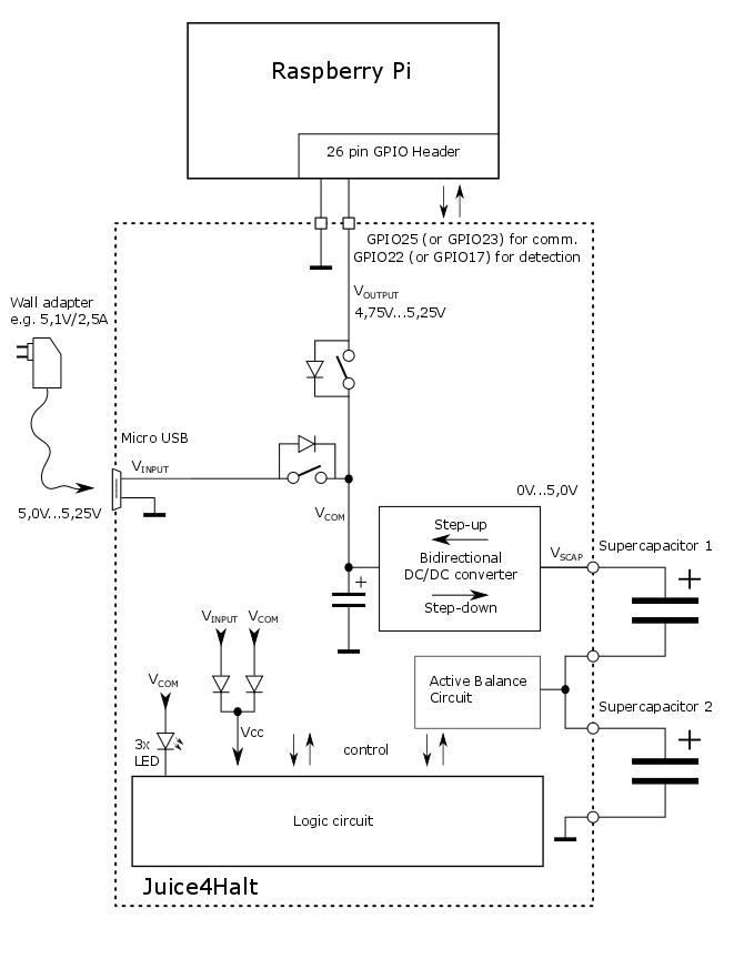
The Juice4halt 5V module is a supercapacitor-based energy storage. It contains a bidirectional step-up/step-down converter working as the interface between the stable 5V supply rail and the supercapacitor. During charging the converter works in step-down mode and transports energy from the external power supply to the supercapacitor. In case of a power failure, the load device (Raspberry Pi or another SBC) is supplied from the supercapacitor via DC/DC converter working in step-up mode.
The Juice4halt HV module is a supercapacitor-based energy storage. It contains two independent DC/DC converters.
The first one is a bidirectional step-up/step-down converter working as the interface between the stable 5V supply rail and the supercapacitor. During charging the converter works in step-down mode and transports energy from the external power supply to the supercapacitor. In case of a power failure, the load device (Raspberry Pi or another SBC) is supplied from the supercapacitor via DC/DC converter working in step-up mode.
The second DC/DC converter is a Front-end step-down converter. The only function is converting a high input voltage down to 5.1V for the 5V rail.
The Juice4halt RTC-485 module is a supercapacitor-based energy storage. It contains two independent DC/DC converters.
The first one is a bidirectional step-up/step-down converter working as the interface between the stable 5V supply rail and the supercapacitor. During charging the converter works in step-down mode and transports energy from the external power supply to the supercapacitor. In case of a power failure, the load device (Raspberry Pi or another SBC) is supplied from the supercapacitor via DC/DC converter working in step-up mode.
The second DC/DC converter is a Front-end step-down converter. The only function is converting a high input voltage down to 5.1V for the 5V rail.
The RS-485 Interface is accessed via a 3-pole screw terminal at the inner side edge of the PCB. The RS-485 Interface is transformed and connected to the UART interface of the Raspberry Pi.
The Real-Time Clock uses a lithium coin battery for power backup when the Raspberry Pi is powered off. The battery holder is situated on the top side of the PCB.
A push-button is used as a Power ON/OFF switch, and perfectly fits into the shutdown and booting scenarios, leading to a function very typical for all laptop-power-on/off buttons or for ATX power supply soft start buttons.


